|
|
||||
|
|
||||
|
|
|
A History of Molecular Representation
|
|
James A. Perkins, M.S., M.F.A., CMI
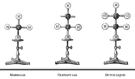
Figure 4. Illustration
of Hoffman's "croquet ball" models which he demonstrated
to the Royal Institution of Great Britain in 1865. Marsh-gas = methane.
Olefiant gas = ethylene. Dutch liquid = ethylene dichloride or dichloroethylene.
(Hoffman, 1865). |
Introduction An increasing number of medical breakthroughs involve the elucidation of molecular mechanisms—cellular communication and signal transduction, the control of gene expression, the molecular basis of the immune response, and so on. Understanding such mechanisms is a critical step in understanding disease and developing new treatment methods. To keep pace with these advances, medical school curricula have shifted attention away from traditional anatomy towards molecular biology, genetics, and pharmacology (Paalman, 2000). To remain on the cutting edge of biomedical communications, the medical illustrator must also possess in-depth knowledge of biochemistry and molecular biology and be able to create accurate depictions of molecular structures and processes. To do this, the illustrator must be familiar with the models and conventions used by chemists to depict molecular structures. Ever since the concept of the molecule was first advanced in the early 1800s, chemists have sought shorthand methods of depicting the composition and three-dimensional form of chemical structures. Chemical formulae, skeletal diagrams, computer renderings, and physical models are abstract representations of the nuclei and electron clouds that make up actual molecules. Since individual atoms are smaller than the wavelength of visible light, we can never know what a molecule really “looks like.” Nevertheless, these abstractions provide a convenient means of organizing our knowledge about molecules, recording the results of research, and communicating new discoveries. More than this, however, the molecular representation is an integral part of the discovery process itself (Hoffmann and Laszlo, 1989; Francoeur, 2000). Once constructed, a molecular representation may reveal properties of the structure that were not apparent from the raw data upon which the model is built. The literature is full of examples of molecular images and models leading directly to new breakthroughs. As one who creates such representations, an illustrator may participate directly in this process of discovery, as well as recording and disseminating its results. This is the first in a series of articles dealing with the historical development of molecular representations. Future articles will focus on contemporary software and illustration methods.
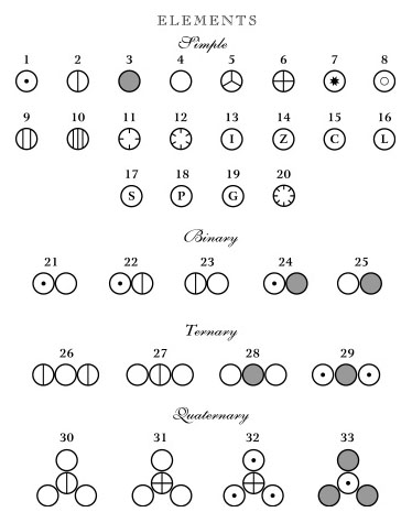
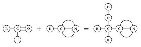
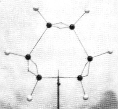
In the early 1800s, John Dalton proposed that all matter is composed of atoms (Dalton, 1808). He could be called the first molecular illustrator, as his publications are filled with drawings of atoms and simple compounds (Figure 1). He developed circular symbols for each of the known elements and represented molecules as clusters of these symbols. He was also the first to develop physical models of atoms and molecules, constructing wooden spheres to represent the atoms (Ramsay, 1974a). Soon after the publication of Dalton’s theory, a number of chemists recognized that atoms combine with one another in regular proportions. Jöns Jacob Berzelius (1813) wrote the first chemical formulae (e.g. H2SO4) as a type of algebraic expression to represent the relative numbers of atoms in a compound. This system had an important advantage over other representations. In the early 19th Century, it was common to print illustrations separately at the end of a book or journal. By constructing his formulae of just numbers and letters, they could be typeset right in the body of the text (Klein, 2001). In 1852, Edward Frankland proposed what would later be known as the theory of valence - that each type of atom can form a specific number of bonds with other atoms. His theory was expanded by Archibald Couper (1858) who showed that carbon is tetravalent (forms four bonds) and can link to one another to form long chains. In his paper, Couper illustrated the structures of common organic compounds, using dashed lines to show the connections between atoms (Figure 2). This convention was later refined by Alexander Crum Brown (1864, 1867) who represented each atom as a letter inside a circle, connected to its neighbors with solid lines (Figure 3). With only minor modifications, these structural formulae remain in use today. The Couper/Crum Brown representation was quickly applied to physical models as well (Figure 4). In 1865, August Hoffmann used a set of croquet balls to demonstrate “The Combining Power of Atoms” during a “Friday Evening Discourse” at London’s Royal Institution (Hoffmann, 1865). He used black balls for carbon (charcoal), “fiery red” for oxygen, white for hydrogen, blue for nitrogen, and green for chlorine. Presumably his choices were dictated by the available colors of croquet balls, but this color convention caught on quickly and is still used today. Two years after Hoffmann’s demonstration, the first commercial set of molecular models was advertised in the journal The Laboratory (cited in Ramsay, 1974b). Unfortunately for Archibald Couper, his mentor delayed publication of his paper on the tetravalence of carbon. Meanwhile, Freidrich August Kekulé von Stradonitz published the same theory a month earlier (Kekulé, 1858) and was ultimately given credit, not only for discovering that carbon forms four bonds, but for the entire concept of valence. Many textbooks still refer to these structural formulae as “Kekulé diagrams,” an unfortunate misnomer (Russell, 1971). Kekulé borrowed the concept of circles and lines to develop his own set of 3D “ball-and-stick” models (Figure 5). Of all the models developed to this point, these were the closest to the ball-and-stick models used today. He used them to great effect to solve the structure of benzene, demonstrating that a carbon chain could double back on itself to form a ring (Kekulé, 1865). They may even have influenced the development of structural chemistry in the latter half of the 19th Century (see below). However, the models had a “fatal flaw,” illustrated by the following story. In 1885, Adolf von Baeyer used these models to demonstrate his “strain theory” of covalent bonds in cyclohexane and other ring compounds (von Baeyer, 1885). His argument is summarized in Francouer (2000):
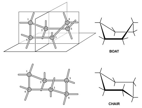
We now know that cyclohexane is not planar and that its bonds are not strained. Instead, the six-carbon ring adopts one of two strain-free, folded forms—the famous “boat” and “chair” models (Figure 6) proposed by Sachse just five years later (1890). Francouer (2000) argues that von Baeyer overlooked this obvious possibility because he was influenced by the models themselves. The bonds in Kekulé’s models were made of flexible rubber tubing or hinged metal wires. This allowed von Baeyer to deform the bonds and force the model into a planar configuration. Had the connectors been rigid as they are today, he could not have forced the cyclohexane model into this shape and may have been forced to investigate other configurations. Thus we have an example of how an abstract representation can influence our thinking about the actual properties of a molecule.
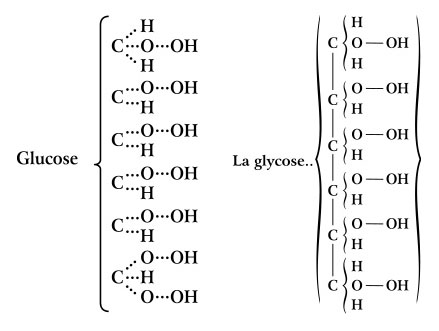
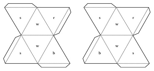
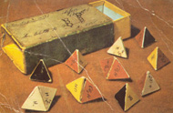
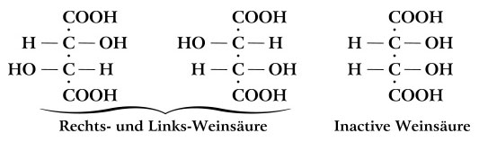
While Couper and Kekulé were correct that carbon forms four bonds, they had no idea how these bonds were arranged in space. Even Hoffmann’s croquet ball models were flat, all atoms lying in the same plane. Interestingly, the carbon atoms in Kekulé’s ball-and-stick models had their four bonds arranged into a tetrahedron. However, this was purely for convenience in drilling the holes and was never intended to show the actual geometry of the bonds (Francouer, 2000). Nevertheless, they may have influenced his students and others who were beginning to explore the 3D arrangement of atoms in a molecule. In 1874, Jacobus van’t Hoff, a former student in Kekulé’s lab, published The Arrangement of Atoms in Space (van’t Hoff, 1874). In it, he demonstrated that the four bonds of carbon form a tetrahedron. He suggested that illustrations of carbon compounds show the carbon atom in the center of the tetrahedron with its four bonded atoms at the vertices. He even provided instructions for building physical models of tetrahedra from cardboard cutouts (Figures 7 and 8). Van’t Hoff’s tetrahedral view of carbon revolutionized the field of organic chemistry. According to Nobel laureate Roald Hoffmann “the tetrahedron is the single most important geometrical figure in chemistry (Hoffmann and Laszlo, 1989: 32).” Among its contributions was an explanation of isomers—compounds that have identical chemical formulae but differ in the arrangement of atoms, resulting in very different optical and chemical properties. Emil Fischer was an early pioneer in the study of isomers, elucidating the various forms of glucose and other sugars (Fischer, 1891). The subtle differences between these forms are only apparent in a three dimensional illustration which shows the tetrahedral nature of each carbon atom. Fischer found it awkward to represent molecules this way in the text of the paper so he developed a representation in which the three-dimensional shape is implied in a flat, two-dimensional figure (Figure 9). At first glance, a Fischer projection, as it is now called, resembles a Couper/Crum Brown structural formula consisting of only letters and straight lines in a flat plane. However, according to Fischer’s convention, the vertically oriented bonds recede into the plane of the paper, away from the viewer, while the horizontal bonds come forward, out of the plane. According to his autobiography (1922), the idea evolved from conversations with his colleague von Baeyer who constructed ball-and-stick models out of toothpicks and dinner rolls. Fischer later used “proper” ball-and-stick models with rubber bonds and pressed them flat to create the two-dimensional projections.
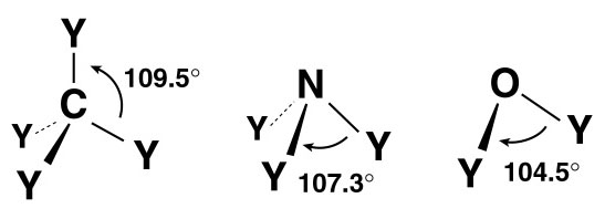
In the late 1800s, the tetrahedral structure of carbon was well established. However, it would be many years before it was clear why carbon formed four bonds in this configuration. The discovery of the electron provided the answer. The theory of Valence-Shell Electron-Pair Repulsion (VSEPR) explains the geometry of bonds through the mutual repulsion of electrons in the outermost shell of an atom. In molecules containing only single bonds, the organic elements adopt the following configurations (see Figure 10):
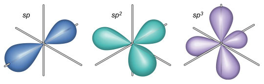
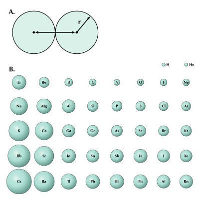
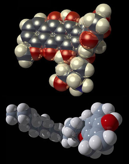
These geometries can be useful for an illustrator when depicting simple molecules without the aid of a computer-generated model. Keep in mind that these angles do not apply to double or triple bonds between these elements. VSEPR provides a simple means of predicting molecular geometry but does not explain why bonds form in the first place. This problem was solved when Linus Pauling (1931) borrowed from the field of quantum mechanics and proposed the hybridization of electron orbitals. Illustrations of dumbbell-shaped orbitals now fill the pages of modern chemistry textbooks (Figure 11). Pauling made numerous other contributions to the field of chemistry (and became the only person to win two unshared Nobel prizes). The contribution that may be of most significance to the scientific illustrator was his description of the der Waals radius (Pauling, 1945). Named for another Nobel laureate, Johannes Diderik van der Waals, this is an approximation of the size of an atom (Figure 12). Strictly speaking, it represents “one-half the distance between two equivalent nonbonded atoms in their most stable arrangement (Chang, 1988: 400).” Put another way, it is the closest that two unbonded atoms can get before they begin to repel one another. When several atoms unite to form a molecule, their collective van der Waals radii provide an approximation of the overall shape of the molecule. This is a useful concept in determining the packing of molecules in crystals and interactions between different parts of the same molecule. To facilitate visualization of molecular shapes, Pauling and his CalTech colleague Robert Corey developed a new type of molecular model (Corey and Pauling, 1953) based on the van der Waals radius (Figure 13). Each atom is represented by a solid sphere, its size proportional to the element’s van der Waals radius. There are no “sticks” because the bonds are obscured by the size of the atoms. Instead, the atoms connect directly to one another with plastic snaps or metal fasteners. These models were later refined by Walter Koltun of the NIH (Koltun, 1965). Now known as Corey-Pauling-Koltun (“CPK”) or “space-filling” models, these are among the most popular molecular models in use today. Scientific illustrators quickly adopted this style to show the overall shape of molecules. The CPK style has also been incorporated into molecular visualization software. The large spheres lend themselves to dramatic lighting effects and produce beautiful illustrations (Figure 14).
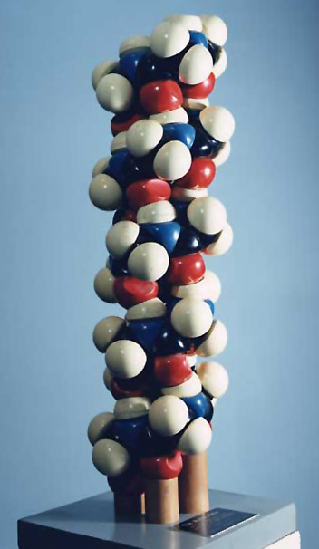
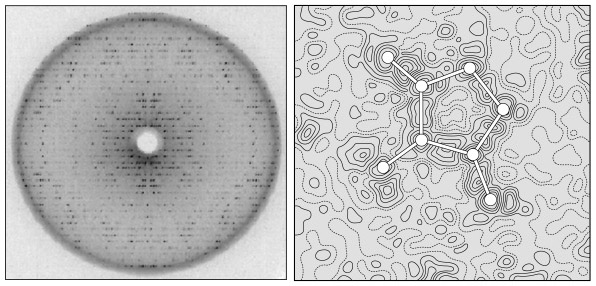
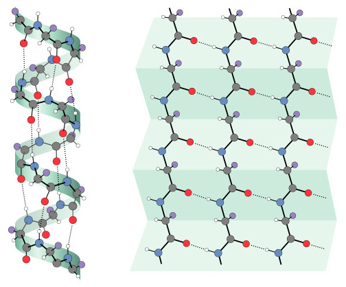
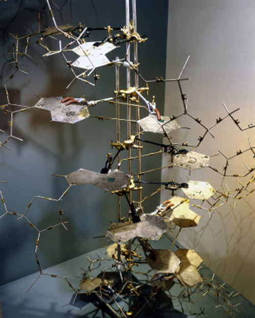
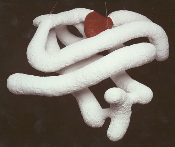
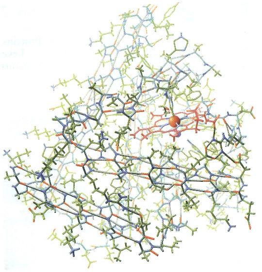
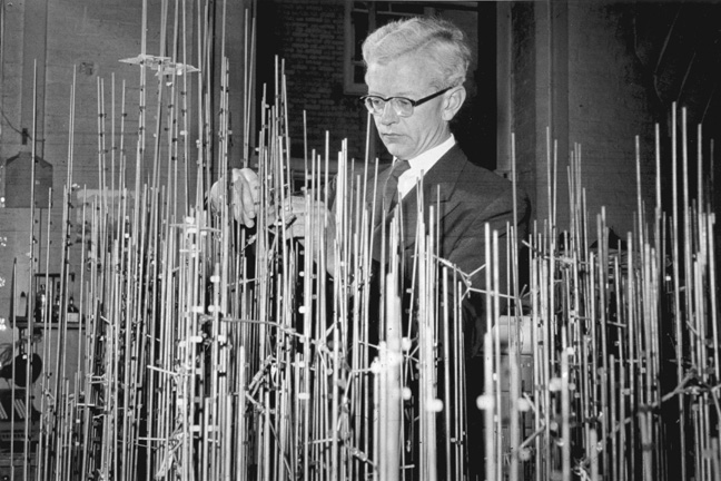
The application of VSEPR principles can determine the shape of small molecules, but they cannot predict the structure of macromolecules such as proteins, nucleic acids, and long-chain polysaccharides (e.g., glycogen). For example, a protein chain folds and doubles back on itself, allowing distant amino acids to interact with one another, forming hydrogen bonds and disulfide bridges. These interactions—and hence the overall shape of a protein—cannot be predicted from the amino acid sequence alone (although many researchers are trying; see, for example, Venclovas, et al, 2001). Other techniques are required to visualize the structure of such molecules. X-ray crystallography is one such technique. In 1912, Max von Laue determined that the wavelength of x-rays (approximately 10-9 cm) is similar to the spacing of atoms in a crystal. He predicted that the regular spacing of atoms in a crystal would function as a diffraction grating, scattering x-ray beams in a predictable pattern (Figure 15). Within a few months, William L. Bragg used this technique to determine the arrangement and spacing of atoms in a crystal of sodium chloride (Bragg, 1912). Beginning in the late 1930s, Linus Pauling and Robert Corey conducted a series of x-ray diffraction studies on single amino acids and short polypeptide chains. At first, they were unable to make sense of the x-ray patterns from peptides of even modest length. Finally in 1951, they found a solution. As the story goes, Pauling began doodling chemical structures on a piece of paper to pass the time while recovering from a bad cold. He twisted the paper to simulate the bond angles of individual amino acids and realized that hydrogen bonds could hold the chain in a helical form. This finally made sense of the x-ray data. They named this corkscrew spiral of amino acids the a-helix (Figure 16; Pauling and Corey, 1951a). Later it was shown that the a-helix is an important component of many proteins. In the same year, Pauling and Corey proposed the b-sheet, another motif common to many proteins (Pauling and Corey, 1951b). When x-rays pass through a solid, they are diffracted by parallel planes of atoms. As a molecule becomes more complex, it contains more planes oriented at different angles. (As an analogy, think of a crumpled ball of aluminum foil. Every tiny flat surface—on the inside and the outside of the ball—represents a different plane). Thus, a complex molecule will diffract x-rays in many directions, producing an extremely complex diffraction pattern. Analyzing such a pattern and converting it into a model of molecular structure is a huge task, requiring a tremendous number of mathematical calculations. When computers became available in the 1950s, it was finally possible to determine the structure of complex macromolecules. In 1953, James Watson and Francis Crick used x-ray data collected by Rosalind Franklin and Maurice Wilkins to solve the structure of DNA. Their announcement, a brief one-page letter in Nature (Watson and Crick, 1953), is one of the most famous in the history of science. What is less well known is the importance of crude wire and cardboard models in their research (Figure 17). Based on earlier x-ray research by Linus Pauling, they originally constructed a triple helix model with the phosphate groups on the inside and the nucleotide bases facing out. After discussions with Rosalind Franklin and viewing her x-ray data, they rebuilt the model as a double helix with the phosphate backbone on the outside and the bases facing in. The only remaining question was the configuration of the bases on the inside of the helix. By tinkering with cardboard cutouts of the four bases, Watson realized that adenine could form hydrogen bonds with thymine and the same was true of cytosine and guanine. Thus, he postulated that the bases on one strand paired with complementary bases on the opposite strand (Watson, 1968). In one of the great understatements in the history of science, they declared in their 1953 paper “[i]t has not escaped our notice that the specific pairing we have postulated immediately suggests a possible copying mechanism for the genetic material.” Five years after Watson and Crick’s famous paper, the first structure of a complete protein was solved using x-ray crystallography. John Kendrew succeeded in crystallizing sperm whale myoglobin and subjected it to x-ray diffraction studies (Kendrew, et al, 1958). At first, he produced a crude model that showed the protein consisting of several long tubes folded into a compact blob (Figure 18). With access to more powerful computers, Kendrew was able to construct a more detailed model of myoglobin (Figure 19) which showed the location of every atom in a chain of more than 150 amino acids (Kendrew, 1961). The tubes turned out to be a-helices. Construction of the detailed model was a tedious, time-consuming process (described in Kendrew, 1961). With over 2,600 atoms, the myoglobin molecule produced more than 25,000 different reflections of the x-ray beam. Converting these reflections to an electron density map required months using the most powerful computers available at the time. As the name implies, an electron density map shows the location of dense clusters of electrons and, thus, the location of individual atoms in the molecule (Figure 15b). It resembles a topographic map, with contour lines indicating “peaks” and “valleys” of electron density. Kendrew and his colleagues created 50 such maps, each one representing a two-dimensional “slice” through the molecule. They drew the maps on slabs of clear lucite and then stacked them up to visualize the molecule in 3D (much the way slices from the Visible Human Project can be stacked up to recreate the human body in 3D). From this 3D electron density map, they constructed a skeletal model (similar to a ball-and-stick model, but without the balls) of the entire protein, including all 2,600 atoms and their bonds (Figure 20).
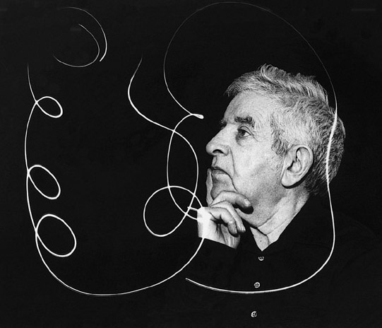
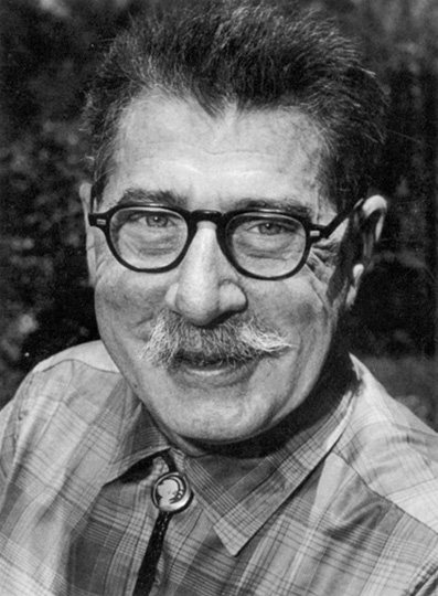
Kendrew’s Scientific American article (1961) on the structure of myoglobin was accompanied by an incredible painting of the molecule by Irving Geis (Figure 19). Without the aid of computer graphics or special visualization tools, he painted the molecule from direct observation of the skeletal model—all 2,600 atoms and their bonds. Nearly forty years later, Martin Kemp reflected on the painting: “Geis gazed with remorseless concentration when painting his portrait of the molecule, using his unrivaled command of perspective, light and shade, and colour recession to reveal the intricate sculptural web of linkages (Kemp, 1998:525).” Working at a time when the first macromolecules were being visualized, Geis was one of the pioneers of molecular art (Figure 21). Born Irving Geisberg in 1908, he studied architecture at Georgia Tech and completed his studies at the University of Pennsylvania, receiving the Bachelor of Fine Arts degree in 1929. There were few jobs for architects during the Great Depression, so he studied painting at the University of South Carolina and began freelancing as an illustrator in New York. During World War II he served as Chief of the Graphics Section of the Office of Strategic Services (a predecessor of the CIA). Following the war, he resumed his illustration career and became a regular contributor to Scientific American, specializing in astronomy, physics, and chemistry (Dickerson, 1997). After painting Kendrew’s myoglobin molecule, he was called upon to create numerous molecular illustrations for Scientific American, including the first structure of an enzyme (lysozyme), cytochrome c, serine proteases, and DNA (Dickerson, 1998; view supporting illustrations). Geis also formed a strong collaboration with chemist Richard Dickerson, illustrating and co-authoring three books: The Structure and Action of Proteins (1969), Chemistry: Matter & the Universe (1976), and Hemoglobin: Structure, Function, Evolution, and Pathology (1983). According to Dickerson (1997) “he became a co-author because I couldn’t afford him as an illustrator.” The Structure and Action of Proteins is a beautifully illustrated book with clear explanations of protein construction and geometry (Figure 22). According to Herbert Bernstein, developer of digital molecular modeling tools, this book “set the standard for hand-drawn, graphical renderings of the features of biological macromolecules (Bernstein, 2000).” The Guggenheim Foundation awarded Geis a grant in 1987 to organize his massive collection of sketches, paintings, writings, and correspondence. He continued this effort until his death in 1997 (Dickerson 1997). In 2000, the Howard Hughes Medical Institute purchased the entire Geis Archive (HHMI Press Release, Oct. 25, 2000). Roger Hayward, a contemporary of Geis, was another pioneer in the field of molecular illustration (Figure 23). He is best known for his collaboration with Linus Pauling, a relationship that lasted more than 30 years. Borne in Keene, NH in 1899, Hayward studied architecture at MIT, receiving the Bachelor of Science degree in 1922. He began illustrating Pauling’s lectures in 1933 and later illustrated several of his books including General Chemistry (1947), College Chemistry (1950) and the controversial No More War! (1958). In 1964, Pauling and Hayward co-authored The Architecture of Molecules (view supporting illustrations). “This beautiful pictorial volume provides a lucid, scientifically accurate introduction to the subject of how atoms are arranged and interconnected in molecules and crystals and to the way in which the geometry of this organization accounts for some of the properties of substances (from the introduction; Pauling and Hayward, 1964).” Hayward’s expertise wasn’t limited to molecular illustration. He was a licensed architect, professional engineer, an inventor with several patents to his credit, and an amateur scientist with several published articles. He was well-known as illustrator of the monthly column “The Amateur Scientist” in Scientific American. These columns, including a few written by Hayward himself, were compiled in The Scientific American Book of Projects for the Amateur Scientist (Strong, 1960). Also an accomplished watercolor artist, he was President of the Pasadena Society of Artists from 1965-1957. He died in 1979. Geis and Hayward set the standard for molecular illustration in the 1950s and 60s, a time when the first macromolecular structures were being solved. In the next installment of this article, we’ll trace the evolution of molecular representation to the present day and discuss the impact of computer visualization on the field of molecular illustration.
Many thanks to Dr. David Goodsell, Dr. Maura Flannery, and an anonymous reviewer for helpful comments and suggestions. Errors are my own. Thanks to the Howard Hughes Medical Institute, MRC Laboratory of Molecular Biology, National Museum of Science and Industry (London), and Oregon State University for permission to reproduce photos and illustrations. Special thanks to the family of Roger Hayward for permission to reprint his illustrations.
von Baeyer, A. 1885. Ueber polyacetylenverbindungen. Berichte der Deutschen Chemischen Gesellschaft 18: 2269-81. Berzelius, J.J. 1813. Essay on the cause of chemical proportions, and on some circumstances relating to them: together with a short and easy method of expressing them. Annals of Philosophy 2: 443-454. Bragg, W.L. 1912. The diffraction of short electromagnetic waves by a crystal. Proceedings of the Cambridge Philosophical Society 17: 43–57. Chang, R. 1988. Chemistry. NY: Random House. Corey, R.B. and L. Pauling. 1953. Molecular models of amino acids, peptides and proteins. Review of Scientific Instruments 24(8):621-627. Couper, A.S. 1858. On a new chemical theory. Philosophical Magazine 4(16): 104-116. Crum Brown, A. 1864. On the theory of isomeric compounds. Transactions of the Royal Society of Edinburgh 23: 234. Crum Brown, A. 1867. On the Classification of chemical substances, by means of generic radicals. Transactions of the Royal Society of Edinburgh 24: 331-339. Dalton, J.C. 1808. A New System of Chemical Philosophy. Manchester, UK. Dickerson, R.E. 1997. Irving Geis: Molecular artist, 1908-1997. Protein Science 6: 2483-2484. Dickerson, R.E. 1998. Irving Geis (1908-1997). International Union of Crystallography (IUCr) Newsletter 6(1): 18. Dickerson, R. E. and I. Geis. 1969. The Structure and Action of Proteins. NY: Harper and Row. Dickerson, R. E. and I. Geis. 1976. Chemistry, Matter, & the Universe. NY: Benjamin Cummings. Dickerson, R. E. and I. Geis. 1983. Hemoglobin: Structure, Function, Evolution, and Pathology. NY: Benjamin Cummings. Fischer, E. 1891. Über die konfiguration des traubenzuckers und seiner isomeren. Berichte der Deutschen Chemischen Gesellschaft 24: 1836. Fischer, E. 1922. Aus Meinem Leben. Berlin: Verlag von Julius Springer. Francoeur, E. 2000. Beyond dematerialization and inscription: Does the materiality of molecular models really matter? HYLE - International Journal for Philosophy of Chemistry 6(1): 63-84. Frankland, E. 1852. On a New Series of Organic Bodies Containing Metals. Philosophical Transactions of the Royal Society. 142: 417-444. van ’t Hoff, J.H. 1874. A suggestion looking to the extension into space of the structural formulas at present used in chemistry, and a note upon the relation between the optical activity and the chemical constituents of organic compounds (translated from Dutch). Archives Neerlandaises des Sciences Exactes et Naturelles 9: 445-454. Hoffmann, A. 1865. On the combining power of atoms. Proceedings of the Royal Institution 4: 401-430. Hoffmann, R. and P. Laszlo. 1989. Representation in chemistry. Diogenes 147: 23-51. Kekulé, F.A. 1858. Liebigs Annalen der Chemie 106: 129. Kekulé, F.A. 1865. Studies on aromatic compounds. Liebigs Annalen der Chemie 137: 129-196. Kemp, M. 1998. Kendrew constructs; Geis gazes. Nature 396:525. Kendrew, J.C. 1961. The three-dimensional structure of a protein molecule. Scientific American 205(6): 96-110. Kendrew, J.C., G. Bodo, H.M. Dintzis, R.G. Parrish, H. Wyckoff, and D.C. Phillips. 1958. A three-dimensional model of the myoglobin molecule obtained by x-ray analysis. Nature 181:662-6. Klein, U. 2001. Berzelian formulas as paper tools in early nineteenth century chemistry. Foundations of Chemistry 3: 7-32. Koltun, W.L. 1965. Precision space-filling atomic models. Biopolymers 3:665-679. Paalman, M.H. 2000. Why teach anatomy? The Anatomical Record (The New Anatomist) 261(1): 1-2. Pauling, L. 1931. The nature of the chemical bond: Application of results obtained from the quantum mechanics and from a theory of paramagnetic susceptibility to the structure of molecules. Journal of the American Chemical Society 53: 1367-1400. Pauling, L. 1945. The Nature of the Chemical Bond. Ithaca, NY: Cornell University Press. Pauling, L. 1947. General Chemistry: An Introduction to Descriptive Chemistry and Modern Chemical Theory. San Francisco: W.H. Freeman. Pauling, L. 1950. College Chemistry: An Introductory Textbook of General Chemistry. San Francisco: W.H. Freeman. Pauling, L. 1958. No More War! NY: Dodd, Mead, and Co. Pauling, L., R.B. Corey, and H.R. Branson. 1951a. The Structure of proteins: Two hydrogen-bonded helical configurations of the polypeptide chain. Proceedings of the National Academy of Sciences 37: 235 240. Pauling, L. and R.B. Corey. 1951b. The pleated sheet, a new layer configuration of polypeptide chains. Proceedings of the National Academy of Sciences 37: 251-256. Pauling, L. and R. Hayward. 1964. The Architecture of Molecules. San Francisco: W.H. Freeman. Ramsay, O.B. 1974a. Molecules in three dimensions I. Chemistry 47(1): 6-9. Ramsay, O.B. 1974b. Molecules in three dimensions II. Chemistry 47(2): 6-11. Russell, C.A. 1971. The History of Valency. Humanities Press. Sachse, H. 1890. Über die geometrischen isomerien der hexamethylenderivate. Berichte der Deutschen Chemischen Gesellschaft 23: 1363. Strong, C.L. 1960. The Scientific American Book of Projects for the Amateur Scientist. NY: Simon and Schuster. Venclovas, C., A. Zemla, K. Fidelis, and J. Moult. 2001. Comparison of performance in successive CASP Experiments. Protein: Structure, Function, and Genetics, Supplement 5:163-170. (Note: CASP = Critical Assessment of techniques for protein Structure Prediction). Watson, J.D. and F.H.C. Crick. 1953. Molecular structure of nucleic acids. Nature 171:737-738. Watson, J. D. 1969. The Double Helix. New York: Atheneum. Wright, R. 1999. Scientists and Thinkers: James Watson and Franicis
Crick. Time. March 29, 1999. |
Copyright 2005, The Journal of Biocommunication, All Rights Reserved