 |
||||
Fifty Years of Anatomy in Fifty Minutes |
| Robert J. Demarest
|
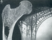
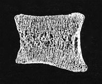
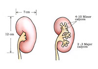
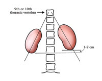
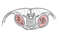
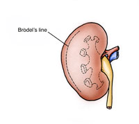
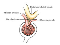
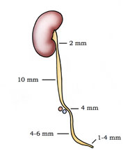
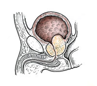
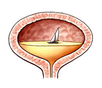
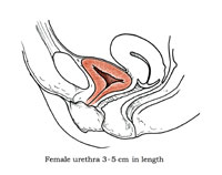
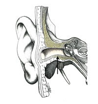
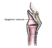
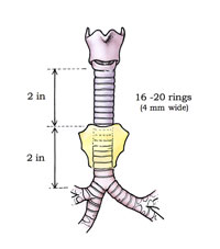
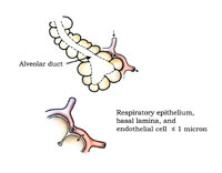
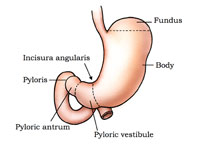
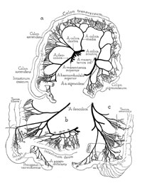
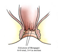
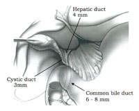
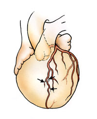
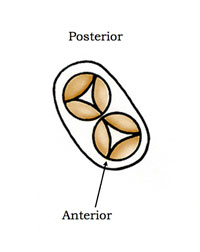
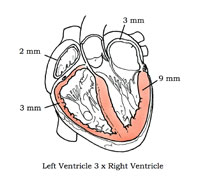
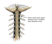
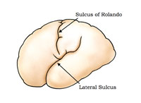
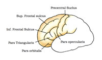
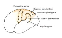
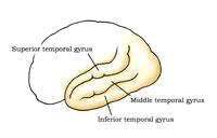
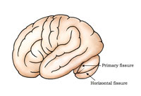
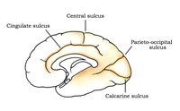
Introduction The following anatomy review is intended to accurately describe the “middle range” of normal gross anatomy, which is the anatomical epitome of the stomachs, kidneys, brains, and hearts that medical illustrators are so often called upon to illustrate. This is not meant to neglect the many variations and anomalies that may be seen during the study of human anatomy, as these variations may be of clinical and surgical importance. However, the focus of this study is to describe the normal anatomical relationships of organs and their conformance to an average. Skeletal System It is easy to find good references for our boney framework. Anatomical atlases abound with excellent skeletal illustrations. However, there is one skeletal area that gets far too little attention – the interior structure of bone. Our untrained competition can, for example, get an atlas and copy a femur quite well, but they don’t know much about the support structure found within the bones. When it comes to sections through a bone, their depictions usually fall short. This takes somewhat more research than most are willing to do. In a section through the femoral head, the trabeculae are arranged in a fashion to support the stress put upon the bone (Figure1). Fritz Kahn, in his 1939 book, Man in Structure and Function, shows a ground section of the femur (from Spalteholtz) along with a picture of an old steel bridge. This is an image that, once seen, stays in your memory bank. In the ground section of the bone one can clearly see the support pattern, and can understand why Kahn used a steel support bridge as a visual metaphor. Also, note the evidence of a growth plate that is still evident in this mature bone. It is the supporting spicules, the trabeculae, which are most often attacked in osteoporosis. This is something to keep in mind when depicting that disease. Don’t lose the structural pattern. In a vertebra, when the internal, vertical supports thin, due to osteoporosis, collapse often results. In the ground section of a normal lumbar vertebra (Figure 2) also note how thin the compact bone is, as it surrounds the internal supporting cancellous bone. This is a good example of normal bone. Illustrators are reminded to resist the tendency to make the compact outer (or cortical) bone too thick – a common error. Urogenital System The seemingly simple urogenital system is very complex (Figure 3). The average size of the kidney is 12 x 7 x 3 centimeters, with the left kidney often being somewhat longer and narrower than the right one. Each kidney has two or three major calyces, and each calyx is divided into four to ten minor calyces, with an average being six. Each of these embraces one, and sometimes two, renal papilla. Knowing this often helps when calculating how many papilla to include in a coronal section of the normal kidney. The kidneys bracket the 12th thoracic to 3rd lumbar vertebrae with the right being one to two centimeters lower than the left (Figure 4). This height placement difference is probably due to some interference by the liver with normal renal ascent during human development. Of particular anatomical interest, the kidneys do not lay against the back wall in a vertical orientation. If you draw a line through the poles of each kidney they will intersect at the 9th or 10th thoracic vertebra (see Anson’s An Atlas of Human Anatomy or Campbell’s Urology) (Figure 4). The kidneys are in an oblique plane, angled toward the front (anteriorly), and tilted. To make this anatomy even more complicated, the medial border is directed forward 30º or more (Figure 5). These relationships make the kidneys difficult to draw, but it also makes our drawings more interesting. The first kidney I ever drew was laying flat in a stainless steel pan in the pathology lab. Far too many are still drawn that way – flat. Medical Illustrator Max Brödel, as a result of careful observations, identified what is commonly called “Brödel’s Line” on the kidney (Figure 6). This is a somewhat avascular line, or zone, that lies at the junction of the posterior and middle third of the kidney. This is an important area relevant to the surgical approach to the renal pelvis. Incidentally, Brödel is, to me, the personification of Marsha Jessup’s “artist-scholar.” See “Personal Note from the Author” at the end of this article. The kidney’s right renal vein is usually direct, single, and relatively uncomplicated. The left, conversely, is usually complex, often passing behind the aorta. Supernumerary arteries are very common. It is so comfortable to depict the renal vessels as single and uncomplicated, but anatomically this is rarely the case. The suprarenal or adrenal arteries have exhibited as many as sixty rami. It is not necessary to show that total number of rami, as only a few accessory vessels can, at times, add a sense of reality to a drawing. No discussion of the kidneys is complete without discussing the glomerulus (Figure 7). This is a structure that we are often asked to illustrate. The afferent arteriole should be made larger than the efferent vessel. A large amount of water is removed from the blood by the glomerulus, and 85% is reabsorbed in the tubules. This probably accounts for the disparity in these arteriole size relationships. The distal convoluted tubule should be illustrated in proximity to the afferent arteriole and, if appropriate to the assignment, include some juxtaglomerular cells and the macula densa in the structure. These cells are found to be in intimate contact with the arterioles and the distal convoluted tubule. This cellular complex is important for the control of the renin/angiotensin system. Ureter The ureter is all too often oversimplified in medical illustrations. The ureter is commonly about 30 centimeters in length, with half above and half below the pelvic brim or true pelvis. Because of the anatomical placement of the kidneys, the right ureter is shorter than the left. Additionally, a ureter is not uniform in shape or caliber, but it has constrictions, and some long spindle-like dilatations along its course (Figure 8). The first constriction is opposite the inferior pole of the kidney. Starting from the renal pelvis, the ureter decreases to about two to three millimeters as it crosses the inferior pole of the kidney. A segment, approximately fifteen centimeters long, runs down the length of the psoas major muscle, where it exhibits a somewhat spindle-like shape until it reaches the pelvic brim. During this descent the ureter widens to as much as ten millimeters in diameter. It constricts to four millimeters at the pelvic brim, where it crosses the common iliac artery and vein. It expands again on the way to the bladder, reaching a diameter of four to six millimeters. Then the ureter may constrict to as little as one millimeter in diameter as it enters the bladder. These constrictions have great clinical significance. They have to be taken into consideration in regard to such things as surgical instrumentation and stents. It is important to note clinically that it is at these anatomical narrowings that renal calculi may often get lodged. For medical illustrators, the varying diameters can add a grace and truthfulness to an illustration that will tower over the even-diameter, rubber tube-like depictions that we see all too often. Also of interest, it was noted in one study of over fifty ureter specimens, that 200 small arteries were found to supply it. The ureter enters the bladder posteriorly near its base. It courses through the bladder wall and enters the interior through slit-like orifices in the corners of the trigone. The trigone is relatively fixed to the floor of the pelvis. It is mostly the dome that expands when the bladder fills with urine. Too often we see illustrations of the ureters entering near the top of the bladder. Remember, the ureters travel sub-peritoneally, and the design does not allow the ureters to move up and down with the expansion of the bladder dome. Clinically, this would cause all sorts of problems. The trigone does stretch a bit with filling, with the orifices moving further apart, laterally. However, this is pretty much the extent of any trigone expansion. Prostate One urinary tract illustration that we are commonly asked to illustrate concerns the prostate, in particular, the condition of Benign Prostatic Hypertrophy, or BPH (Figure 9). We’ve all seen the all-too-frequent ads on TV for some BPH controlling drug, with the prostate growing as we watch. There’s not much space below the bladder in the male pelvis. A great deal of the hypertrophy is upwards into the bladder. This growth compromises both the lumen of the membranous urethra and space within the bladder itself. In particular, a region called the Transition Zone is responsible for the hypertrophy. This is an anatomical area just below the bladder and lateral and posterior to the urethra, reaching as far down to the verumontanum. This upward growth can act as a dam-like barrier and leave residual urine in the bladder. The verumontanum is an important landmark during transurethral resection (TURP) of the prostate. Surgeons strive to stay above that structure when they core out the prostate. Fortunately, that saves the sphincter while taking out most of the hypertrophic prostate. One common error seen in bladder illustrations is what I refer to as the bladder’s “lake effect.” This is amusing, but I am including a comment about this error, because I’ve seen this too many times (Figure 10). There is no air in the urinary Urethra In the female the urethra is only four centimeters long, on average, or about 1½ inches (Figure 11). It is drawn much too long all too often. Its entire length is muscular, forming one continuous sphincter. There is really no conspicuous urethral sphincter seen in either the male or the female urethra. Before we leave this area I will append a small note about the testes in the male. The left is usually lower than the right in about 70% of the population. An illustrator should not depict the testes directly opposite each other, as is sometimes seen. Respiratory System In a mid-sagittal section through the head, remember to depict the nasal cartilages correctly. This lateral cartilage feathers out under the nasal bone. The alar cartilages then override this. This later cartilage is important physiologically during a nasal respiratory phenomenon called “valve effect,” wherein slightly pressurized air is directed over the nasal turbinates. Ear canal The ear canal is often illustrated in a coronal section. Nature has strived to protect the tympanic membrane from direct injury, so the canal structure is something other than a straight tunnel (Figure 12). You enter the ear canal going forward and upward, and then back in a serpentine fashion. Of interest is the boney floor and roof portion. This boney area is only about a centimeter and a half long. Before reaching the tympanic membrane, this boney platform forms the narrowest portion of the ear canal, thereby protecting the tympanic membrane from trauma. The canal should not be depicted as an even tube, and should include some narrowing at the boney portion. The Larynx One of my favorite organs is the under-appreciated larynx (Figure 13). This little structure makes it possible to eat and drink through the same passage that supplies air. A lesser-known fact is that the larynx also enhances physical labor. The audible grunt often heard when a player hits a serve on the tennis court is from air being expelled after an “effort closure” of the larynx – the release of air that has been trapped to stabilize the upper body. The entire shoulder girdle, as you know, is attached, ligamentously, only at the sterno-clavicular joint. Accordingly, the stabilization of the upper body is important for strenuous physical recreation or work activity. The larynx rising quickly within the thyroid cartilage, and thereby closing the air passage, brings about “effort closure.” Closing off the air passage on swallowing is somewhat different. There is an epiglottal tubercle on the epiglottis, seen in mid-sagittal section as a bulge, which acts as the fulcrum for the folding. It is similar to the dimple in a child’s cricket toy. This anatomical bulge may be somewhat difficult to see unless you are looking for it, but it adds to your illustration and is important anatomically. Instead of drawing a straight little cartilaginous disc, put a nice lower curve into it. Trachea The trachea begins where the larynx ends, at the lower border of the cricoid cartilage, on a level with the 6th cervical vertebra (Figure 14). The trachea crosses five vertebral bodies – one cervical and four thoracic. Seen from an anterior view, the trachea is located behind the sternum with the sternal notch positioned at the middle of the trachea. The trachea courses for approximately two inches above and two inches below the sternal notch. Additionally, remember that the aorta deflects the trachea slightly to the right. The trachea has from 16 to 20 rings, most of which are about four millimeters in height. The membrane connecting the rings measures a little over one millimeter in height. The first ring is usually larger than the rest and often partially fused with the cricoid cartilage. More distally, the bifurcation of the trachea has a carina or “keel.” The carina is the cartilaginous ridge within the trachea that runs anteroposteriorly between the two primary bronchi. The carina supports the anatomical bifurcation of the trachea. As the trachea divides into a right and left bronchus, the bronchi do not come off symmetrically. The right is less angled than the left, most probably because the aorta has pushed the trachea toward the right, and more of the heart is on the left. It is my belief that the only time you might be excused for drawing the bifurcation symmetrically is in a graphic design. Also, the right bronchus is slightly larger than the left (the ratio is 5:4), because the right lung is larger. The position and size difference may account for the fact that the right bronchus is the most common location for inspired foreign objects. It is more of a straight run from the trachea to the right main bronchus. Persons trying to catch a tossed peanut or other edible in their mouth, often end up with the particle lodged in their right main bronchus. The right bronchus divides into three main bronchi and the left into two. The left upper lobe bronchus corresponds to the right upper and middle bronchus, while the two basals are roughly equal. The cartilaginous rings supporting the airway cease to exist shortly after entering the lungs, but smaller cartilaginous plates continue down to where the diameter of the bronchioles reaches one millimeter. The terminal bronchiole becomes the respiratory bronchiole, and more distally form the alveoli. The alveoli are visible to the naked eye. They are physiologic air sacs, which, if you make a cast of them with Wood’s metal, as we did as students, they look like small bunches of grapes (Figure 15). The entire lung parenchyma is filled with alveoli. The word alveoli is derived from the Latin for “small hollow.” The alveolar wall is very, very thin, which facilitates the exchange of oxygen for carbon dioxide. The tendency for illustrators is to represent this wall too thick. For clarity, the alveolar wall consists of a respiratory epithelial cell, the basal lamina, and the endothelial cell of the capillary. In total, this thickness is less than a micron. Too often I have drawn it so that it looks like a section of a plastic coffee cup. I realize that one must show some thickness in a structure, but the tendency is to make this much too thick. Digestive System Esophagus The esophagus, while a vertical tube, should not be illustrated as being straight. It begins at the bottom of the pharynx and veers slightly to the left. Then comes back to the midline at the level of the fifth thoracic vertebra, before heading strongly to the left again. The esophagus is narrowest at the beginning and at the end, and exhibits a slight bulge before it enters the stomach. Be careful in depicting the cardiac sphincter at the esophagogastric junction. It is more of a physiologic sphincter than a muscular one. The stomach for all its variability has distinct parts, and we should be familiar with them (Figure 16). Of course, every time you see a stomach, viewed upright or prone, full or empty, it will look different, but it is not simply a shapeless blob. Illustrators should include certain landmarks such as the fundus, the body, the incisura, the pyloric vestibule, and the pyloric antrum. These anatomical divisions give a stomach illustration some character. As we progress further down the intestinal track, we come to the small and large intestine. Because of the tendency to exaggerate when we are concentrating on a structure, some illustrators may make the intestinal walls too thick – sometimes pathologically thick. The wall thickness depends upon whether the structure is relaxed or contracted. On average two millimeters is an appropriate thickness for the wall of the large intestine. I always remember taking a colonoscopy tour through an actual patient and being surprised at how the liver was visible by its color, as the colonoscope passed beneath it. The intestinal wall is thin enough at that point for the liver color to be evident. As a reference for the blood supply to the intestines I have found nothing better than the old Barry J. Anson, Atlas of Anatomy (W.B. Saunders Co., 1951). This anatomy text is still available on the book find sites. Of course, there are other more complete angiographic atlases, but they are usually very expensive and, to me, somewhat more confusing. Anson shows, with variations, the anatomy of the most common patterns of the intestinal arterial supply (Figure 17). By using a reference such as this, you will soon become familiar with the main arteries, the branches, and arches they form. This reference will describe how distinctive the vasculature is in each area. In preparing a drawing of a section through the rectal canal, an illustrator will need to show the rectal columns, or Columns of Morgagni (Figure 18). These columns are the remnants of the embryologic cloacal membrane, and they number from six to ten. Accordingly, in any coronal, or sagittal section, only three or four columns would probably be visible. Again, some illustrators have a tendency toward overemphasis when doing an illustration. It is interesting that in an illustration in my old Gray’s Anatomy, the rectal canal is shown with a large number of these columns, and in the legend it is written that the illustration has shown too many. Cystic, Hepatic, and Common Bile Duct In examining the liver and gallbladder, you will find that the associated ducts exhibit distinctive anatomy with specific size relationships (Figure 19). The cystic duct is approximately three millimeters in diameter, the hepatic duct is four millimeters, and the common bile duct is six to seven millimeters in diameter. So, if you make the common bile duct twice as wide as the cystic duct, you will be safe. The hepatic duct should be drawn just a little larger than the cystic duct. Circulatory System An important anatomical feature of the heart’s vasculature that is often misrepresented relates to the branching of the Left Anterior Descending Coronary Artery, which supplies the heart’s left ventricle. The LAD artery does not have significant branches over to the right side of the heart. In plastic injection corrosion specimens of the coronaries you will see little or no overlap. Netter, in his Ciba Collection Volume 5, Heart, has a depiction, based on arteriography, that shows this pretty clearly. I have based my illustration on Netter’s (Figure 20). Notice that the small branches coming off what looks like the right side are perforating interventricular branches. These are often seen on an arteriograph and, depending upon the view, can be mistaken for branches to the right ventricle. These interventricular branches supply the anterior two-thirds of the septum. I would like to emphasize that we shouldn’t show the LAD arborizing, and sending large, obvious branches over to the heart’s right side. This is something we see incorrectly illustrated too often. As we age, there is an increase in anastomoses between the right and left coronaries. However, much of this anastomosis is confined to the epicardial fat. The British Gray’s Anatomy includes an injected specimen showing this division with the interventricular branches so well, that they obscure the truth at bit. The fact that there is very little overlap is a factor in coronary artery disease. If the LAD artery is compromised, the right coronary is not going to offer much assistance. A groove can be seen on the anterior surface of the pulmonary artery that reflects the site of attachment of the pulmonary valves within. A cross section through the embryologic heart shows how the aortic and pulmonary valves form in a symmetric fashion and the imprint of their attachment remains (Figure 21). One grievous error that you will occasionally see is an illustration, which depicts a right coronary vein accompanying the right coronary artery, on its way back to the aorta. As you know, the right coronary veins empty directly into the right atrium. Heart - Coronal Section Another common illustration is a coronal section through the heart. It is often used to show how the blood flows through the chambers (Figure 22). All too often the right ventricular wall is shown too thick. The proportions are 3:1. The left ventricle is three times thicker than the right. Commonly, the thickness averages about three millimeters for the right and about nine millimeters for the left. This anatomical difference is compatible with the function that each ventricle has to perform. The septum is composed of elements of each, with the septal arteries feeding down an unseen divide. I like to show the septum just slightly thicker than the left ventricular wall, and bulging slightly into the right ventricular chamber. Remember too, that the heart’s left atrium carries fresh oxygenated red blood returning from the lungs while the right carries un-oxygenated blood. Due to the thin atrial walls, the left will show, in life, a healthier, redder color. The left atrial wall is slightly thicker than the right – about three millimeters for the left, and two millimeters for the right. The Nervous System The Spinal Cord There are 31 pairs of spinal nerves. That includes one coccygeal root, five sacral, five lumbar, twelve thoracic, and eight cervical nerves. There are eight cervical because root number one starts above the first cervical vertebra, although sometimes anatomically there is not much of a first cervical root. Then things get into proper order, and accord with the vertebra above each root. The point of the accompanying illustration is to show that the spinal cord is not segmented by groups of nerve rootlets. Motor and sensory nerve rootlets enter and exit the cord in a continuous, evenly-spaced distribution (Figure 23). The rootlets come off the cord in a continuum, and are gathered into nerve roots much the way you can gather the fringe on a tablecloth into neat groups. Never show more anatomical space between any two roots than you would show between the rootlets themselves. Distal Spinal Cord At birth the cord ends at the level of L3, while the adult cord ends between L1 and L2. The sub-arachnoid space below L1 is occupied by the Cauda Equina. The spinal cord does not extend the complete length of the canal. This anatomical area enables an anesthesiologist to administer spinal anesthesia blocks and perform spinal taps with a minimum of danger to the cord itself. The Brain Each individual’s brain is, as you know, quite different. We all became aware of this in about third grade. There is an anatomical pattern that can aid in our depiction of the human brain, if we know what to look for. Two thirds of the cortical surface of the brain is hidden in the sulci. In the evolution of the brain, the increase in white matter was less than the needed increase in the gray matter. So, the increased gray matter just bunched and folded into our white matter core. There is a pattern to the confusion of grooves seen over the brain’s surface. Obviously, an illustrator may vary this somewhat, but behind the variation there is a general anatomical pattern, which should be understood. The Sulcus of Rolando extends from the medial surface, slopes forward, and ends just short of the Lateral Sulcus (Figure 24). The large Frontal Lobe is divided by three sulci (Figure 25). The first one is the Precentral Sulcus; second is the Superior Frontal Sulcus; and third is the Inferior Frontal Sulcus. Remaining are the Precentral Gyrus and Frontal Gyri. The Inferior Frontal Gyrus is further divided by gyri running up from the Lateral Sulcus into three parts. Those parts are the Pars Opercularis, the Pars Triangularis, and the Pars Orbitalis. The Pars Triangularis is fairly constant and along with the Pars Opercularis is known as Broca’s Speech Area. The Parietal Lobe is divided by two major sulci called the Post Central Sulcus, and the Interparietal Sulcus (Figure 26). These sulci divisions provide the anatomical landmarks for Superior Parietal Lobule and the Inferior Parietal Lobule, as well as the Post Central Gyrus. The Inferior Parietal Lobule is further divided into the Supramarginal Gyrus and the Angular Gyrus. The Occipital Lobe has no named gyri on the lateral aspect, but often there does appear a Lunate Sulcus. The Temporal Lobe is divided by two sulci, the Superior and Inferior; hence the lobe has three gyri – Superior, Middle, and Inferior (Figure 27). The Cerebellum has only two common landmark fissures: Primary and Horizontal, which dominate the subordinate fissures on its surface (Figure 28). The brain’s medial surface can be divided into the Limbic, Frontal, Parietal, and Occipital Lobes by the Cingulate Sulcus and the Parieto-occipital Sulcus (Figure 29). By appreciating the brain’s underlying structure and its consistent surface landmarks, an illustrator will have an increased understanding of the individual patterning of each brain. Conclusion Fifty years bent over a drawing board, observing in the operating room, or dissecting a specimen, is bound to increase one’s understanding of the structure and function of the human body. I do not pretend to be an expert anatomist, but I most certainly am an awed admirer of how we are built and how we function. I remember the delight I experienced whenever I discovered something new, or saw some small feature that would make my illustrations a bit more accurate, hence a bit more useful, than they were previously. It is in this spirit that this review is presented. Bibliography Anson, Barry J. 1951. An Atlas of Human Anatomy, W.B. Saunders Co. Kahn, Fritz and George Rosen. 1939. Man in Structure and Function. Netter, Frank H.1969. The Ciba Collection of Medical Illustrations: Volume 5, Heart, Ciba-Geigy Corporation. Patrick Walsh and Campbell, Meredith. 1986. Campbell’s Urology, W.B. Saunders Co. Spalteholz, Werner and Rudolf Spanner. 1967. Spalteholz-Spanner Atlas of Human Anatomy, 16th edition, Edited by Rudolf Spanner. English Edition, translated and prepared by A. Nederveen and G. N. C. Crawford. London: Butterworths. Williams, Roger and P. Williams (Editors). 1975. Gray’s Anatomy, British Edition.
I was fortunate throughout my career to be associated with a great medical center, Columbia-Presbyterian, in New York. My studio/office was, for most of my tenure, just fifty feet from the anatomy dissection lab. There was a medical museum down the hall, filled with wet specimens and models, and I was fortunate in having the staff of the medical center available and eager to be helpful. With all that, I had an insatiable curiosity, and a love for the study of anatomy and related subjects. My wife used to joke that I would take an anatomy book to bed at night in preference to a good novel – that was true. When I retired from Columbia I continued to be involved in my field as the medical art director of various medical journals. My job was to sketch concepts and check the anatomical accuracy of the illustrations. This sort of work had started before my retirement. With Modern Medicine in the 1980’s, I was responsible for cover concepts. Later, I worked with MediVisuals, Inc., checking medical-legal illustrations for accuracy. Next, I was with the Journal of the Cleveland Clinic for six years. For the past four years, I worked with Dowden Health Media Publications. Dowden produced four different journals and I was involved, to some degree, with the illustrations used in all of them. I had the privilege of working with many AMI members in my capacity as art director. Many times I learned more from my colleagues than they did from me. In recent years this work kept me close to the AMI and many of my friends. Last year, I finally called a halt to a career that consumed, in one way or another, over fifty years of my life. All of it was a labor of love. I finally quit so that I could spend some years doing fine art, something I had neglected throughout my life as a medical illustrator. I might add, I wanted to spend more time wading some great trout streams both here and abroad. The driving force behind much of my work was a desire to produce drawings that were anatomically correct. Without a doubt, the study of anatomy is a lifelong pursuit. We, as trained medical illustrators should promote and sell accuracy to our clients everyday. Unfortunately, too many non-medical artists are selling themselves in our field – an arena where they don’t belong. I have seen the results on television, seen it in newspapers, seen it in lay magazines, and in medical journal ads – medical illustrations that were inaccurate, yet slick, and in their smooth inscrutability, and all too saleable. In1990, the AMI’s then President, Marcia Jessup, in her Presidential Address, beseeched illustrators to emulate the scholar-artists of ancient China and Korea. She said that they were “few in number and the most influential of men” (in those days, and in their culture, it was mostly men). Being known as “artist scholars” should be our goal, and we should continually remind our clients of that description. It is our biggest asset. With good promotion and constant reminders of our unique training, we can trump any untrained copyist. This article is based upon a paper presented at the Association of Medical Illustrator’s Annual Meeting in Indianapolis held in July 2008. The article’s title, Fifty Years of Anatomy in Fifty Minutes, reflects the length of the original presentation. In order to preserve the presentation’s original flavor and intent, this article retains Mr. Demarest’s candid commentary, personal insight, and keen anatomical observations. |
Copyright
2009, The Journal of Biocommunication, All Rights Reserved
Table
of Contents for VOLUME 35, NUMBER 1